Automated,
Menu Driven Drawings We make
automated drawing sets for our customers. Here is an extremely successful
example. These
techniques have been useful when large quantities of similar drawings have
to be created. In this case, a detailed drawing for a moment foundation,
like that used in a pier or a large sign pole, can be commissioned in 15
minutes or less once the base drawing is set up. This compares favorably
with 2 to 4 hours for a unique structural drawing. The customer using this drawing set freed up drafting resources,
since the only values to change were selected from a drop-down list on a
Microsoft Excel spreadsheet. The bolting, base plate, anchor plates and
rebar were determined in advance by engineering, and change with the size
of the column and foundation. The changes are reflected in the
drawing without having to change leader notes, dimension lines, or any
other drawing parameter. This
particular automated drawing made it possible to crank out hundred of
drawings for an installation crew, and the crew always knew how much rebar
to make up and how much concrete to order. This
drawing series also enabled fast turnaround on installation quotes, and
eliminated lag time between sales, engineering and field services. We can
also automate sheet metal drawings so that the flat pattern, complete with
bend allowances, can be sent to a CNC laser or turret punch, or a complex
milled part can be interpreted by CAM software for use in a CNC mill.
Entire assemblies can be driven from menus to create instructions for the
factory floor or service manuals. A few
simple steps generate the drawing: Open the
Autodesk Inventor part, assembly, and drawing files, as well as the MS
Excel spreadsheet. Select
the column size, footing diameter and footing depth desired from the drop
down menu in the MS Excel spreadsheet, and hit “Save”. Refresh
and save the part, assembly and drawing in Inventor. The proper solid model
now appears. Print it
out…use it for quotes (there is a complete, auto generated BOM and bolting
spec in the drawing), code approvals and construction. The weld
specifications are also listed in this example. The drawing is in a form that
is ready to checked and stamped by a local structural P.E.
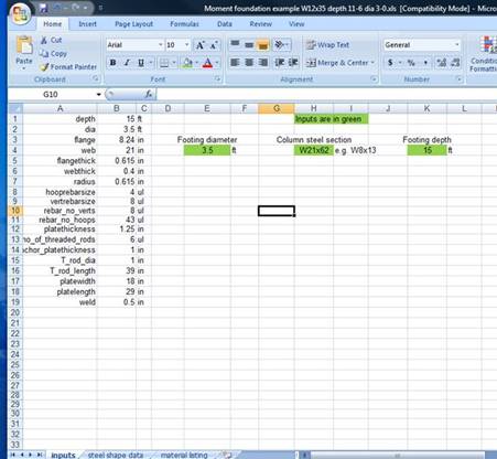
Enter the column and footing size in the spreadsheet…
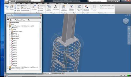
Open and refresh the solid model part and assembly files…
And out pops the drawing, complete with bill of materials.